Need wiring help

Disclaimer: Links on this page pointing to Amazon, eBay and other sites may include affiliate code. If you click them and make a purchase, we may earn a small commission.

chuckles

Full Access Member
Joined
Sep 25, 2014
Messages
118
Reaction score
0
Location
Ashland, KY
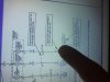
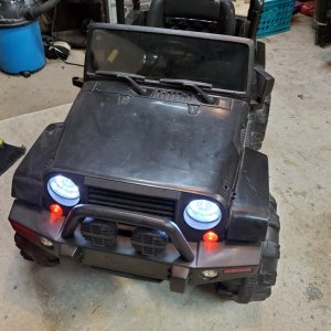
Here are my wires coming from the harness and which way they go. I also listed where each were went on the driver side (DS). If you guys can just help me understand which of the 4 wires that go to the passenger side (PS) get split and go to each spot on the bulb sockets I should be set to go!!! Thanks so much for all the help these past few days! I really feel like it's almost licked!

Black w/yellow stripe to DS
Green w/red stripe to DS
Solid black to DS
Solid blue to both sides
Black w/white stripe to PS
Green with yellow stripe to PS
brown w red stripe to PS

DS marker black w/yellow on clip side & green w/red outside

DS blinker green w/red on clip side, black w/yellow in middle, black on outside

DS fog solid black on R when looking at back of bulb and solid blue on L


I also looked at the drive side marker and which harness locations those wires originated from then went to the opposing side of the harness clip and followed that color back to my passenger marker. When doing this I found that on one wire it looked correct (if my theory is correct on opposing positions it the harness) but on the other wire the one I though should be going to the marker did not. Maybe the wire that powers the marker when the headlights are on is correct on the PS but the wire that controls the blinking isn't. If so then ive found my issue. Im excited to get back out there tomorrow and tinker more, gonna go look at the FSM myself right now and try to understand these diagrams while waiting for someone smarter to chime in!
 
Last edited:

profdlp

Counting My Blessings
Staff member
Moderator
Joined
May 21, 2013
Messages
5,817
Reaction score
1,766
Location
Westlake, Ohio
A "mess" is right. :shocked:

Oh, well - at least you'll know it was done right once you get it straightened out. :)
 

uss2defiant

Full Access Member
Joined
Jun 25, 2014
Messages
3,597
Reaction score
152
Location
Tucson, Arizona
PS
DG/YL goes from junction box pin 30 to side marker pin 1 and turn signal pin 2.
BR/RD goes from side marker pin 2 to turn signal pin 1 which is also in series with pin 3 of the hazard switch/combination flasher connector.
BK/WT goes to ground

DS
BK/YL goes from from junction box pin 28 to side marker pin 1 and turn signal pin 2.
DG/RD goes from side marker pin 2 to turn signal pin 1 which is also in series with pin 7 of the hazard switch/combination flasher connector.
BK goes to ground
 

chuckles

Full Access Member
Joined
Sep 25, 2014
Messages
118
Reaction score
0
Location
Ashland, KY
the answers to your questions are all in the wiring diagram from the FSM.

I just struggle understanding them sometimes is all....im reading it now but if you guys can post to it would help me confirm as I go. Thanks again

And I see you listed brown/red goes to marker light....that's what I thought too if I remember correctly from my "opposing pin theory" It also ISNT what they had done so I hope that's my issue right there!
 
Last edited:

uss2defiant

Full Access Member
Joined
Jun 25, 2014
Messages
3,597
Reaction score
152
Location
Tucson, Arizona
follow the color code on the good side to figure out what pin is what.
Use that as a reference for the listed color code for the bad side.
 

chuckles

Full Access Member
Joined
Sep 25, 2014
Messages
118
Reaction score
0
Location
Ashland, KY
PS
DG/YL goes from junction box pin 30 to side marker pin 1 and turn signal pin 2.
BR/RD goes from side marker pin 2 to turn signal pin 1 which is also in series with pin 3 of the hazard switch/combination flasher connector.
BK/WT goes to ground

DS
BK/YL goes from from junction box pin 28 to side marker pin 1 and turn signal pin 2.
DG/RD goes from side marker pin 2 to turn signal pin 1 which is also in series with pin 7 of the hazard switch/combination flasher connector.
BK goes to ground


Theres a 4th wire too....not being out there to look I think its blue and goes to the fog light. What is the other color that also should go to the fog?
 

uss2defiant

Full Access Member
Joined
Jun 25, 2014
Messages
3,597
Reaction score
152
Location
Tucson, Arizona
DS marker
BK/YL is pin 1
DG/RD is pin 2

DS blinker
DG/RD is pin 1
BK/Yellow is pin 2
BK is pin 3

PS marker
DG/YL is pin 1
BR/RD is pin 2

PS blinker
BR/RD is pin 1
DG/Yellow is pin 2
BK/WT is pin 3
 

chuckles

Full Access Member
Joined
Sep 25, 2014
Messages
118
Reaction score
0
Location
Ashland, KY
anything else while I'm still awake? I answered all your questions.


Nope you got them all, and u answered my blue wire question while I was asking it. I am already using my good side diagram I had drawn and comparing it and I think it all looks like it should in my head while I was sitting out there! Thanks so much, if your ever in my neck of the woods the beer is on me! Appreciate ALL the posts these past few days!
 

uss2defiant

Full Access Member
Joined
Jun 25, 2014
Messages
3,597
Reaction score
152
Location
Tucson, Arizona
I'm using the 03 FSM.
again, again, again, refer to section 8w-52-4 and 8w-52-6.

NP.
It's very difficult to follow without understanding the references and the references go every where.
 
Last edited:

chuckles

Full Access Member
Joined
Sep 25, 2014
Messages
118
Reaction score
0
Location
Ashland, KY
sent you pm w/ my cellphone number.
i'll be still up studyin so send me txt if you need more help

Thank you sir! I was after 3am when I stopped and went to bed so didn't want to text you to say I appreciated due to time difference.

One more thing to do and that's go buy a role of wire to finish the job, I think its 18gauge if I understand the FSM correctly. Does that look correct?

Only other thing I plan on doing is to go to Napa Monday for some new body/fender flare clips, plastic rivets etc so I finish up this job correctly since is all apart as it is. When the collision repair was done I see they improvised on a few things and figure I will do it correctly while I can. Ill let you know when im finished and how it turns out.
 

chuckles

Full Access Member
Joined
Sep 25, 2014
Messages
118
Reaction score
0
Location
Ashland, KY
I went and bought a roll of 18g wire because I thought that's what I read on the FSM but the wire said on the back of the package its in tended for single filament bulbs. The 16g wire said dual filament bulbs, turn signals, break lights and other items. Someone double check my math for me and look at the FSM and make sure the 18g wire is proper for everything on that harness please. I will be powering the marker lights, turn signals, and fog lights. 3 of the 4 wires on the harness are also split to go to multiple fixtures. Just wanna make sure I didn't miss a step in the FSM and the 18 is good for all the fixtures and splits etc. I would just use the 16 to be sure but would hate to cause some sort of additional draw on the harness by accident or something down the road. I don't plan on EVER getting back into this location again so I wanna do it right the first time.
 

uss2defiant

Full Access Member
Joined
Jun 25, 2014
Messages
3,597
Reaction score
152
Location
Tucson, Arizona
Last edited:

chuckles

Full Access Member
Joined
Sep 25, 2014
Messages
118
Reaction score
0
Location
Ashland, KY
there's nothing in the FSM about what gauge to use.
Use an AWG chart to figure out load rating for the wire gauge you are using and what the expected loads are.
If you have 18 AWG that's about 16A for chasis wiring.

American Wire Gauge table and AWG Electrical Current Load Limits with skin depth frequencies and wire breaking strength

If you need more just put two 18AWG in parallel to double that current rating.


I swear I read in the "legend" at the front of the wiring section that wire gauge was indicated on the diagrams. I will go look now and take apic of what I am talking about. Hold a second.
 

chuckles

Full Access Member
Joined
Sep 25, 2014
Messages
118
Reaction score
0
Location
Ashland, KY
Look at page 675 on the FSM and at the attached pic. This is what I'm talking about. Isn't " size " referencing wire size?
 

Attachments

  • image.jpg
    image.jpg
    98.1 KB · Views: 7

Members online

No members online now.
Top