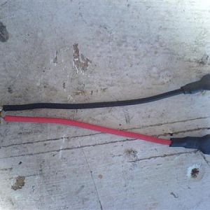
ok just cleaned all battery connections as well as the ground.
im just learning how to use a multimeter, so this is neat yet, im kinda lost. i got a little over 12 v on my new battery. cranked it, and got less. so i understand this shows no charging is going on. pretty simple.
i did a diode test on the negative bat cable to where it grounds at the body and it passed. i also checked from the main lug on the alt and also got the same v reading as the battery so i now know the fusable link is good.
so now, how do i bench test the alternator? and how can i diode test the small wire that plugs into the back of it?
I am not with you when you say "cranked it and got less"....while the engine is cranking the starter motor draws a lot of current so you expect the voltage to drop over the battery...as long as it does not drop below about 10 volts which indicates a bad battery. if the engine starts and runs then you expect that the voltage over the battery will go up to about 13.5 volts which means it is charging.
I am not sure what you mean by "diode test"....this setting on a Multi meter is used to test diodes.
I think what you are trying to do is a "continuity" test which means that you set the meter to "Ohms"...touch the red and black lead together to check that you are getting 0 Ohms or very near to it...then you check the continuity or resistance between two points ie. the negative lug of the battery to chassis where you would expect next to 0 Ohms....the positive side of the battery would need to be disconnected at this stage as when testing for resistance there should be no outside current involved. you can then do the same procedure with this time the negative lead disconnected and check from the positive battery lug to the alternator. Neither of these tests prove much though because you are drawing next to no current through the meter....under the 600 A or so that the battery carries while turning over the starter motor then even a slight bit of bad contact on the battery clamps causes a major voltage drop there.
You need to check that you have a very good, charged battery.
The battery terminals need to be clean and tight...use sandpaper to clean the contact areas. Do the same with the contact of the negative lead to chassis and both sides of the grounding strap that grounds the engine to the chassis.
All that these steps will do is ensure that while the engine is cranking...there is not such a large voltage drop that the PCM only gets about 10 volts supplied to it so that it cannot function.
The PCM controls the charging voltage by Pulse Width Modulation on the field coil of the alternator.....in other words the one side of the field coil should go straight to +12 volts from the battery while the "ground" side of the field coil is switched On/OFF continously in PWM mode by the PCM...the PCM sends a square wave of negative voltage to the field coil in varying durations...the more time the pulse is negative...the more current flows....the PCM can under heavy load switch this lead to ground completely to get maximum charge from the alternator....this is how you can actually Bench test the alternator..supply +12 volts directly across the field coil to get maximum voltage out of the alternator!
Let me post up some circuit diagrams with some marked positions of what you expect to get on your meter....I am assuming the Jeep starts and runs but does not charge?
I also assume that this is a 2006 KJ with the 3.7 L gas engine?
Edit to add: I see that the 2006 KJ Gas model circuit diagram shows that on the field coil a Black wire goes direct to ground (via some connectors) while the Brown/dark green wire actually gets switched ON/OFF by the PCM!
Yet if you read the Theory of Operation that comes with the Service Manual that this circuit diagram is a part of they give the same explaination as I gave ie. that the Ground is switched ON/OFF....this is not new that there are major discrepancies in the Jeep documentation!
I am waiting to hear if this is a 2006 CRD or 3.7 Gasser before I post the diagrams with advice on what to check!