
Sephiroth
Full Access Member
So I've been driving for about a year with no cluster lights, everything else works in the cluster except the back lights. this started after I replaced my heater core. I thought I might have pulled a wire out of its connector or perhaps even ripped it but I did not get around to looking for it til now.
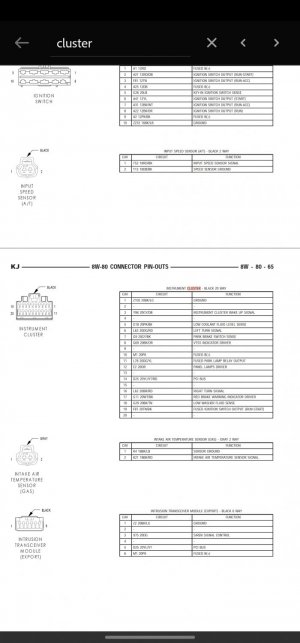
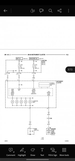
After looking at the pinouts for the cluster and the dimer switch I deducted that pin #12 orange is the one responsible for sending positive voltage and pin #1 black/green is ground completing the circuit, however when i supply ground to #1 and 12v to #12 directly at the cluster nothing happens? or at least not that I could see during the day; and when testing #12 orange wire at the harness I found that it is grounded at the junction block.
Am I reading the diagram wrong? Shouldn't #12 orange be positive?
testing at the dimer switch makes no sense either. pin #1 orange /red should be responsible for sending the signal to turn on the panel lights, testing for continuity shows an open circuit, applying 12v does nothing.
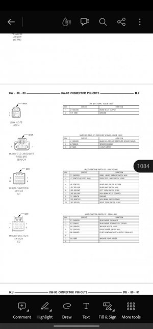
All fuses are good, all panel lights burning out at the same time is unlikely, applying 12v at multy function switch does nothing so not likely a bad switch? now that I think about it I did not actually test pin 1 to ground but if it was bad I guess nothing on the cluster would work at all...
Any ideas appreciated
After looking at the pinouts for the cluster and the dimer switch I deducted that pin #12 orange is the one responsible for sending positive voltage and pin #1 black/green is ground completing the circuit, however when i supply ground to #1 and 12v to #12 directly at the cluster nothing happens? or at least not that I could see during the day; and when testing #12 orange wire at the harness I found that it is grounded at the junction block.
Am I reading the diagram wrong? Shouldn't #12 orange be positive?
testing at the dimer switch makes no sense either. pin #1 orange /red should be responsible for sending the signal to turn on the panel lights, testing for continuity shows an open circuit, applying 12v does nothing.
All fuses are good, all panel lights burning out at the same time is unlikely, applying 12v at multy function switch does nothing so not likely a bad switch? now that I think about it I did not actually test pin 1 to ground but if it was bad I guess nothing on the cluster would work at all...
Any ideas appreciated