
Se7enLC
Full Access Member
Summary
Install a CB radio or other interior low-power 12V device (radar detector, GPS, etc) without splicing factory wiring. This is NOT recommended for powering lights or any other high-power or exterior device, devices like those should be powered through a relay, which is not covered in this howto. Some adjustment to the instructions may be needed depending on the location of the device to be powered.
Parts List
Tools Needed
Procedure
Install a CB radio or other interior low-power 12V device (radar detector, GPS, etc) without splicing factory wiring. This is NOT recommended for powering lights or any other high-power or exterior device, devices like those should be powered through a relay, which is not covered in this howto. Some adjustment to the instructions may be needed depending on the location of the device to be powered.
Parts List
- Littelfuse Add-A-Circuit for Mini Fuses or similar:
http://www.partsexpress.com/pe/showdetl.cfm?&DID=7&Partnumber=071-585
You must be registered for see images
This can probably be purchased from a local VIP, AutoZone, Pep Boys, etc. - 16 or 18 gauge wire, red and black
- Paired DC Power connectors. I used the Vanco BL-1:
You must be registered for see images
but you can easily use spade or other wire connectors, or just direct-wire if you want. If your device has a power connector instead of bare wire leads, you should use a matching connector if possible. - Round flat eyelet crimp connector:
You must be registered for see images attach - Electrical Tape
Tools Needed
- Multimeter highly recommended
- Soldering Iron + solder or butt-connectors + crimp tool
- Adjustable wrench
Procedure
- Remove the side kickpanel on the drivers side (the panel where the hood release is). It should just clip out.
- Remove the drivers side knee bolster. It should pop down and slide to the side to be removed.
- Remove the plastic fuse box cover on the left side of the dashboard (acessible when the door is open).
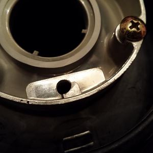
- Locate the grounding bolts. under the kick panel. You will see other things grounded to these.
- Crimp the eyelet connector to one end of a length of black wire.
- Set the eyelet on the grounding bolt (where you will later bolt it) and run the wire up into where the knee bolster covered.
- Crimp the add-a-fuse lead onto the end of a length of the red wire
- Plug the add-a-fuse into the fuse box in place of the cigarette lighter fuse. Do not put a fuse into the add-a-fuse unit, yet.
- Route the red wire to the same location as the black wire, under the knee bolster.
- Making sure that wire from the ground strap and from the add-a-fuse unit are routed cleanly and without too much slack, tape the two wires together where they meet (not electrically-taped, just so that the two wires are stuck to eachother.
- Run the wires under the trim panels to the location of the device. This may require removing additional trim panels, such as the radio trim panel.
- When both the black and red wires are routed to where you want them and the right length is available to plug into the device, cut the wires to that length.
- To attach the connector to the end of the wire, you can pull the wires back out and bring the entire assembly to a table to solder on, or if you are crimping, you may be able to crimp the connectors in place.
- If you are using a keyed connector like the vanco one shown above, make the red (hot) wire be the one that is not exposed (to prevent accidental grounding when the device is disconnected.
- If you are using individual connectors, use one that has a plastic hood for the red wire and if possible, use opposite genders for red and black to prevent accidental polarity swapping.
- Attach the opposite gendered connectors to the wired leads coming off the device (solder or crimp)
- Bolt the ground connector to the grounding bolt
- Insert a fuse into the add-a-circuit unit (10A or less recommended)
- Plug the add-a-circuit unit into the fuse box in place of the cigarette lighter fuse (make sure to plug the cigarette lighter fuse into the add-a-fuse unit in the other fuse connection)
- Before attaching the device, it is recommended that you test the voltage output of the connector. You should see somewhere between 12 and 14 volts.
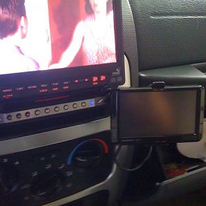
- Attach the device and try it out.
- If it works, tape up the wiring or use zip ties to clean things up.
- Reattach the trim panels that you removed.