
iamweasel
Full Access Member
Riiight, I've been planning this build for ages now and I finally got all the bits together that I need. (I won't mention that someone who will remain nameless, threw away the first batch of LEDs I ordered)
We've all seen those ridiculously over-priced LED light bars:
http://www.rigidindustries.com/product-p/eseries30.htm
Well, here's a guide on how to build your own LED spots. I'm building two spots - not a light bar, but the parts I'm using would perfectly suit a rectangular lightbar.
This setup will (in theory) generate the same amount of lumens as the 30" $1000 lightbar above (12000lm). I know I know, lumen values aren't a direct measure "brightness". Luiminous intensity - "brightness" - is a factor of how those lumens are focused
....Aaaaanyway, the optics I've chosen give similar beam angles to the Rigid Industries (R.I. for future reference) light bar , so the 'brightness' should be comparable.
Parts:
I'm gonna use fibre glass to recreate the OEM shape.
If you wanted a R.I. style lightbar, you can find lots of aluminium extrusions at your local hardware store that would work.
The cost? about $100.
The LEDs:
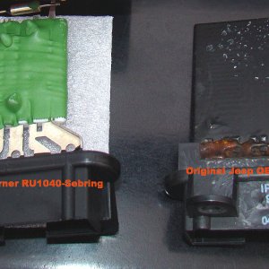
The Heatsinks:
The optics laid out on the heatsink:
As you can see above, the optics definitely lend themselves to the RI style lightbar. I'm pretty sure they use the same optics.
The optics come in these holders:
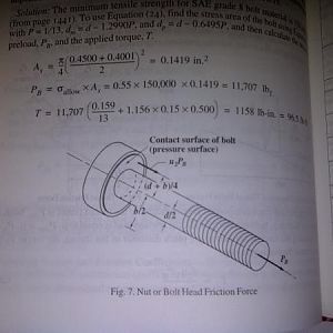
Some of my calculations to determine the required beam angles:
The sketch on the left is a top-down view, showing the beam width at certain distances: 50m, 100m and 200m. I aimed for a 20m-wide beam at each of those distances. I'll have to wait for a trial run to see if my speculations on these beams angles are correct.
The optics are cheap though - about $1 a piece - so changing the beam angles is no biggie - cheap and easy.
Circuit diagram of the power supply:
I'll be tweaking this to run 3 LEDs in series, not 2 as show here. LEDs need a constant current, so this bit is crucial. I looked all over the net for a suitable DC-DC transformer, but ended up with the plan to make one from a circuit design I found online.
Step 1: Prepare the heatsinks for the LEDS
The heatsinks I ordered had a ridge on them which I had to grind down.
The smoother/flatter the better the heat transfer will be. Each of these LEDs is 10W, so good heat dissipation is necessary.
Decide on a layout and drill holes for the LEDS:
Step 2: prepare the optics
I wasn't able to get hold of Ledil optics specifically for the Cree XML LEDs, so I ordered ones for a similar Cree LED. A bit of Dremel-work was necessary...
Typically the LEDs would be screwed directly to the heatsink, but this can cause shorting issues between the LED, screws and heatsink.
What I decided to do, is screw through the optic holders and LED board, into the heatsink. like this:
That's as far as I got this weekend...
Next steps:
Shout if you have any questions")
We've all seen those ridiculously over-priced LED light bars:
http://www.rigidindustries.com/product-p/eseries30.htm
Well, here's a guide on how to build your own LED spots. I'm building two spots - not a light bar, but the parts I'm using would perfectly suit a rectangular lightbar.
This setup will (in theory) generate the same amount of lumens as the 30" $1000 lightbar above (12000lm). I know I know, lumen values aren't a direct measure "brightness". Luiminous intensity - "brightness" - is a factor of how those lumens are focused
....Aaaaanyway, the optics I've chosen give similar beam angles to the Rigid Industries (R.I. for future reference) light bar , so the 'brightness' should be comparable.
Parts:
- 12 x CREE XML T6 LEDs
- 12 x Ledil optics (each spot: 2x 8° spot, 2x 14°x46° oval, 2x 6°x24° oval)
- 2 x PC cpu heat sinks (Aluminium is really expensive here, so this was the only cost effective option, but I found a few US heatsink companies on Google)
- 1 x constant current power supply (I'll describe this in detail later)
- switch
- relay
- thermal paste
- 3mmX9mm self-tapping screws
- wiring
I'm gonna use fibre glass to recreate the OEM shape.
If you wanted a R.I. style lightbar, you can find lots of aluminium extrusions at your local hardware store that would work.
The cost? about $100.
The LEDs:
You must be registered for see images
The Heatsinks:
You must be registered for see images
The optics laid out on the heatsink:
You must be registered for see images
As you can see above, the optics definitely lend themselves to the RI style lightbar. I'm pretty sure they use the same optics.
The optics come in these holders:
You must be registered for see images
Some of my calculations to determine the required beam angles:
You must be registered for see images
The sketch on the left is a top-down view, showing the beam width at certain distances: 50m, 100m and 200m. I aimed for a 20m-wide beam at each of those distances. I'll have to wait for a trial run to see if my speculations on these beams angles are correct.
The optics are cheap though - about $1 a piece - so changing the beam angles is no biggie - cheap and easy.
Circuit diagram of the power supply:
You must be registered for see images attach
I'll be tweaking this to run 3 LEDs in series, not 2 as show here. LEDs need a constant current, so this bit is crucial. I looked all over the net for a suitable DC-DC transformer, but ended up with the plan to make one from a circuit design I found online.
Step 1: Prepare the heatsinks for the LEDS
The heatsinks I ordered had a ridge on them which I had to grind down.
The smoother/flatter the better the heat transfer will be. Each of these LEDs is 10W, so good heat dissipation is necessary.
Decide on a layout and drill holes for the LEDS:
You must be registered for see images
You must be registered for see images
Step 2: prepare the optics
I wasn't able to get hold of Ledil optics specifically for the Cree XML LEDs, so I ordered ones for a similar Cree LED. A bit of Dremel-work was necessary...
Typically the LEDs would be screwed directly to the heatsink, but this can cause shorting issues between the LED, screws and heatsink.
What I decided to do, is screw through the optic holders and LED board, into the heatsink. like this:
You must be registered for see images
You must be registered for see images
You must be registered for see images
That's as far as I got this weekend...
Next steps:
- Solder the LEDs into circuits of 3 LEDs in series.
- Test using a 220v power supply connected to the mains (I bought one specifically for this. Puts out 36v @ 3A.)
- TEST I'll post some videos/pictures
- Build and test the 12v power regulator
- Test again using the Jeep's power
- Build the enclosures
- Assemble!
Shout if you have any questions